Add Bearings...
The Add Bearings... option allows you to add the bearing or azimuth of each line in a line feature theme to its record in the attribute table. You can subsequently subset the line features by querying the attribute table and defining a range of suitable orientations. You can then make a raster from the subset by buffering the selected lines using the Spatial Analyst Distance... menu selection.
Azimuth can be used where directed linear
features are important; bearing used where non-directed linear features are
important. Both bearing and azimuth of multi-point lines (polylines) are the
length-weighted average of their segments. This applies to well-behaved curved
lines.
Bearing is reported in the intervals -90 to 90 where -90 is west, 0 is north and 90 is east. Azimuth is reported from 0 to 360 measured from north in a clockwise direction; so 90 is east, 180 is south, and 270 is west.
The bearing and azimuth are stored in an attributes named SDMBearing and SDMAzimuth, which are added to the end of the attribute table for the line shapefile.
Note that these definitions are inverted from the usage in ArcSDM3.
![]()
To calculate bearings for a line theme:
1. Select Add Bearings... from the ArcSDM3 menu.
2. Select the line theme you want to process from the dialog and select the bearings or azimuths:
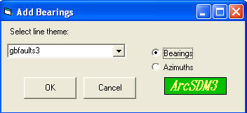
3. Click 'OK'.
| Top of Section | Home |
![]()